IPX
Introduction
Netware origins stem from Xerox Network Systems (XNS) and is currently at version 5. At
the network layer the Internetwork Packet Exchange (IPX) is used to provide a connectionless
service, and at the transport layer Sequenced Packet Exchange (SPX) is used for services
requiring connections. (SPX is equivalent to UDP or PEP). Higher up the OSI model is the
NetBIOS emulation offering an interface between the operating system and the lower level
network services. Routing Information Protocol (RIP) and Service Advertising Protocol (SAP)
are Netware Core Protocols (NCP) which provide an application level interface to the Netware
file system. SAPs are used by Netware 3.X and 4.X running bindery emulation whereas Netware
4.X and 5 running NetWare Directory Services (NDS) do not use SAP so much, the initial GNS
still occurs as normal as this is required for the client to gain entry into the NDS.
There can be several servers doing different jobs on the same network. Although they would
all share the same network address; they would have the following distinct characteristics:
- Server name: Between 2 and 47 characters can be used for Netware 3.1X and above.
- Internal network address:
- MAC address: The 6 byte address burnt on the Network Interface Card (NIC).
- Server Type: Print Server, File Server, Application Server etc.
Addressing
Each network has an external address consisting of 8 hexadecimal digits ranging from 00000001 to
FFFFFFFE (4 bytes), also some routing devices have an internal address or ID number. Although
this address looks like the external address, it is unique to the file server and identifies
the file server's internal virtual network in memory. This virtual network logically extends
the file server's operating system to link the Netware Loadable Modules (NLMs in Netware 3.X)
or Virtual Loadable Modules (VLMs in Netware 4.X). RIP and SAP advertise the internal network
address. (NLM replaced the previous Value Added Process or VAP).
Novell Routers
There are three types of routers:
- Internal router: This exists within a file server and can have up to 4 NICs with
each one having to have a unique network address as well as the router itself having a unique
internal address.
- Dedicated external router: This can be a normal DOS PC and have up to 4 NICs each
one having a unique network address, the PC can no longer be used as a workstation and there
is no need for an internal network address.
- Non-dedicated external router: This is the same as above but must have a unique
internal address, it can be used as a workstation.
Netware operation

The file server allows users to share network services, devices and network applications
which are downloaded to the user (client) before execution. The user boots the workstation
from DOS, loads the IPX stack which contains a NIC driver and the IPX protocol stack, and loads
one of a number of shells. The loaded shell modifies the DOS interrupt vector table adding
Netware compatible software interrupts acting as an interpreter for workstation commands.
When data is created at a source machine the following steps occur:
- An NCP header is added onto the data packet.
- The IPX header is added by IPX.COM.
- The device driver then adds the MAC header and the completed packet is sent across the media.
- The destination machine, on reception of the packet, removes the MAC header.
- IPX.COM strips off the IPX header.
- NCP/IPX removes the NCP header.
The Initial Connection

In the above diagram you can see how the Novell server has its servers (File, Print etc.) sitting on a virtual
network 8 with an internal MAC address of 0000.0000.0001. There is a software router that sits
between the servers and the actual LAN.
The following sequence occurs for client to server communication:
- The client boots and the IPX stack is loaded.
- The shell program is loaded into memory. This consists of IPX.COM and NETX.COM.
- The shell sends a SAP broadcast looking for the nearest available server. This is called
a Get Nearest Server (GNS).
- The server receives the packet and sends a SAP unicast response to the client address.
This is called a Give Nearest Server. The client receives
and keeps in its memory the server type, name, internal address, MAC address, communications socket address
and the number of hops it is to the server, this forms an entry in the SAP table. At this stage, the client
does not know the way to network 8 and the internal address of the file server, which is
always defaulted to 0000.0000.0001.
- The client's shell now sends out a broadcast RIP request called a Get Local Target to find the route to the server.
- When the server gets the request it returns a unicast RIP response called a Give Local Target
to the client. In the above case the response says that you can
get to network 8 via BEAD.123.456.789 which is the external address of the server NIC.
The client compares the returned network number with the one that it received in the Give Nearest Server response earlier.
If the network numbers are the same then the client knows that the server is on the same network. However, if
the network numbers are different, then the client sends another RIP broadcast request to which the router(s)
respond with the known routes to this server.
It is so important that RIP traffic is not denied the clients across routers.
Now, the client knows the network address to the server, the number of hops to the server and
the amount of ticks (1/18th second) it takes.
- The shell next sends an NCP request to create a connection with the server.
- The server responds with an NCP response packet and an assigned connection number.
- The shell finally sends a Proposed Packet Size NCP request telling the server the maximum
allowed packet size (usually 576 bytes).
- The server replies with an NCP response to make sure that the packet size that the client
outputs is the same size as that of the server's NIC.
- Once connected the client can now see the virtual drive F: and now logs on to a file server using the two utilities
LOGIN.EXE and ATTACH.EXE. LOGIN transmits the username and password to the particular file server.
On authentication, there is some handshaking where a connection number is assigned to the Shell (on the client) and the
client and server negotiate a maximum packet size that either can accept.
Subsequent connections to other servers in the network occurs via this log on server using the logon server's
bindery.
NetWare Serialisation packets are used by NetWare to ensure that illegitimate
copies of the server software are not being copied across the network. To all fileservers, every 66 seconds, NetWare servers transmit
a unicast packet containing a serial number.
Router Operation in a Routed IPX network
The router builds it's routing and service tables by listening to the RIPs and SAPs from the
various servers in the network. If a client sends a SAP (get nearest server) and a server
exists on it's own network, then the router will ignore the SAP since, from it's tables, it
knows that there is a local server, however, if no server exists on that LAN, then the router
uses it's server tables and responds to the client with a SAP containing the network and IPX
address of the nearest (or least number of ticks, or failing that, alphabetical order) server
offering the required service. Also included in the SAP response is the server name, internal
address, type, socket number and network count.
The client now sends a RIP broadcast to find the best path to the server, the IPX header's
destination network address is 00000000 (unknown), however within the packet the destination
server's network address can be found. The router responds to the client with a RIP response
containing the server's internal network address the hop and tick counts.
The client now sends an NCP request to the file server containing the router's MAC address
as the destination address, the destination internal address will be the file server and the
NCP request connection packet. The router forwards the packet on to the required server.
Once routing tables and service advertising tables have been built up, routers send out
updates to keep these tables up to date. This uses up bandwidth so one technique to reduce
the use of bandwidth is to use the Best Route Algorithm and another is Split Horizon.
Information learned from a particular interface is never advertised out of that interface
including any advertisements. Routing and service updates occur every 60 seconds and when
there are changes within the network. It is wise to prohibit RIP and SAP updates across an
expensive WAN link so the WAN RIP Period and the WAN SAP Period should be set to
'0' which stops the 60 second periodic updates but still allows the initial and final updates
to occur. Split Horizon should also be enabled to minimise traffic as long as the network
is point to point or fully-meshed (i.e. every router has a connection to all other routers).
In a non-fully meshed network Split Horizon should be disabled so that each node can learn
about all routes to each network.
The Best Route Algorithm states that if two paths exist, then the best route is the one with
the least ticks. If the routes have the same number of ticks then the route with the least
number of hops is chosen, routers then only advertise the best route. If multiple equal
cost paths to a destination exist then the MAXPATHS parameter could be changed from '1' to
'2' so that the router will multiplex data down both paths rather than the default one path.
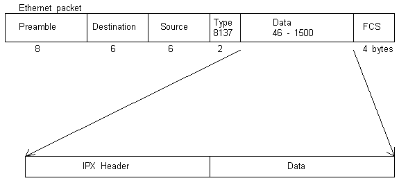
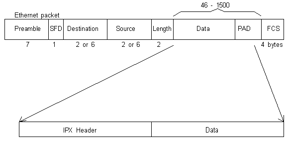
Novell Encapsulation
Refer to the Ethernet
document for in depth discussion on the ethernet frame itself.
Encapsulation within Ethernet II:
Encapsulation within 802.3:

The DSAP byte is the Destination Service Access Point and the SSAP byte is the Source Service Access Point,
both sometimes referred to as Logical Service Access Points (LSAPS) and identify the upper-
layer packet types. One bit is used for control which, in the DSAP, indicates whether the
destination address is an individual or group address and in the SSAP it indicates whether
the Protocol Data Unit contains a request or a response frame. 'E0' indicates that a Novell
IPX header is contained within the information field.
The High Level Data Link Control (HDLC) defines that the Control field contains '01' for
information, '02' for supervisory frames and '03' for unnumbered frames. Netware always
sets this to '03'.
Encapsulation within 802.3 Raw Frame:
The 802.3 frame format was designed to be used with the LLC 802.2 header, however IPX was
developed before 802.2 was so the 802.3 frame was used without the LLC 802.2 header (hence
RAW). LSAP and SNAP are now common and are recommended for encapsulation rather than the
RAW frame format.
Encapsulation within 802.3 SNAP:
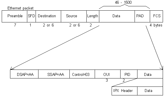
Because the TCP/IP world and Apple wanted more space for the protocol identifiers (DSAP and
SSAP not being large enough at 1 byte each), Subnetwork Access Protocol (SNAP) was developed
to provide a five-byte Protocol Identification (PID) field and set the SSAP/DSAP fields to 'AA'
so that routers will see that and go to the PID for the protocol type information. The OUI
field contains the first three bytes of the MAC address which represents the Vendor code.
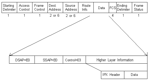
Encapsulation within 802.5:
For a detailed look at the Token Ring frame refer to the Token Ring document:
Internetwork Packet Exchange (IPX) Header
A connectionless service is when a process uses IPX to communicate with a node when no link
between the two is established. There is no guarantee or verification of delivery and each
IPX datagram is a separate entity with no relation to any other IPX datagram.
Every network segment has a unique network address. Because a node may have a number of
processes running Socket numbers are needed to distinguish each process and forms
the basis of the intranode address, so that packets received by IPX which are addressed
to the socket, are passed on to the particular process.

- Checksum: Matches the XNS standard having a value of FFFF.
- Packet Length: 30 bytes to 65535 bytes in theory (originally 576 bytes).
- Transport Control: How many routers has this packet passed through on it's way
to it's destination and is set to zero by the sending node and if it reaches 16 the packet
is discarded.
- Packet Type: For example, in Decimal:
- 0 - unknown
- 1 - RIP
- 4 - SAP
- 5 - sequenced packet (SPX)
- 17 - NCP
- 20 - NetBIOS WAN broadcast!
- Destination Network: Internetwork routers should not set this to 00000000 since
this will assume that the packet is destined for the same network as the source. FFFFFFFF is
not allowed.
- Destination Node: The physical (MAC) address of 6 bytes. FFFFFFFFFFFF means an
all nodes broadcast.
- Destination Socket: The socket numbers represent different processes within a node. Common socket numbers include:
- 0x451 - File Service Packet
- 0x452 - SAP
- 0x453 - RIP
- 0x455 - NetBIOS packet
- 0x456 - Diagnostic packet
- 0x457 - Serialisation packet
- Source Network: Sending nodes set this to 00000000 meaning the source network is
unknown, routers receiving this then fill this in with the correct adress before forwarding the
packet.
- Source Node: This is the 6 byte physical address, FFFFFFFFFFFF is not allowed.
- Source Socket: All Netware file servers have the same socket addresses but requests
may come from any socket.
IPX RIP
A RIP packet can contain from one (40 bytes) set of network number information to fifty sets
(432 bytes) and is used for the following:
- For workstations to find the fastest route using a route request.
- For routers to update their internal routing tables using a route request.
- Reponding to route requests.
- Periodic broadcasts making other routers aware of current configuration.
- Broadcasts that occur on network changes.

- Operation Field: Shows whether the packet is a request ('01') or a response ('02').
These could be a General request, a Specific request, a General response, a Specific response
or an informational broadcast.
- Network Number: This four byte field contains the network address assigned during
installation and can be 1 to 8 hex characters.
- Hop Count: This is ignored in a RIP request packet, a hop count of 16 is unreachable.
- Tick Count: One tick is 1/18th of a second and ticks are used for estimation of the
time it takes to deliver a packet to a particular node. Drivers assume that LANs with more than
1Mb/s of bandwidth have a delivery time of one tick and the driver periodically polls remote
segments in case there are any changes.
Spilt Horizon is used for advertising RIP and SAP information so that information coming in
on a particular interface will not be advertised out of that interface. Only the initial
and final RIP broadcasts should be sent out of a WAN interface NOT the 60 second broadcasts.
If, after 90 seconds, no response from the RIP occurs, a futher 90 seconds is allowed before
deleting the router address from the routing table.
Service Advertising Protocol (SAP) Header
File Servers, Print Servers, Queue Servers etc. are services that need to be advertised to nodes
along with their network addresses. A SAP Agent builds a Server Information Table and updates
the file server's bindery. It is essential for a workstation to obtain the address of a server
before it can access any services, the client maintains a cache table of up to seven servers
and their addresses.
A SAP is used for the following:
- A client request for the name and address of the nearest type of server required.
- A general request by a router for names and addresses of all servers.
- A response to a nearest server request or general request.
- 60 second periodic broadcasts.
- A broadcast of changed server information.

- Operation Field: As well as '01' and '02' (see RIP) there is '03' for Get Nearest
Server Request and '04' for Get Nearest Server Response.
- Service Type: '0000' - Unknown, '0003' - Print Queue, '0004' - File Server,
'0005' - Job Server, '0007' - Print Server, '0009' - Archive Server, '0024' - Remote Bridge
Server, '0047' - Advertising Print Server and above '8000' is reserved.
- Server Name:
- Network Address:
- Node Address: MAC address of the device on which the server resides.
- Socket Address: The socket number on which the server will receive requests.
- Hops to Server: The number of intermediate routers that the packet has passed.
SAP information is broadcast on to each network every 60 seconds using Split Horizon and the
same rules apply to SAP as to RIP. One SAP packet can advertise up to 7 different services.
Follow this link to a list of IPX SAP numbers.
Network Basic Input/Output System (NetBIOS)
This was initially developed by IBM to run on their broadband LAN and used to be encoded in
a ROM on the NIC, however nowadays, in Token Ring networks, NetBIOS is loaded using the IBM
LAN Support Program disk. Reference the link NetBIOS for more
detail.
Netware Core Protocol (NCP)
So far we have seen various frame types 802.3, 802.5, SNAP etc. and the encapsulation of IPX
within them and the further encapsulation of RIP, SAP and NetBIOS within IPX. NCP is how
Netware clients and servers communicate and is encapsulated within IPX. The clients transmit
NCP messages via the Netware Shell to do with file reads/writes, job queues, drive map settings,
directory searches etc. After the initial connection sequence (see earlier) the server replies
to each single NCP request with an NCP reply.

Request types can be; 1111 - create a service connection; 2222 - service request; 5555 -
destroy service connection; 7777 - burst mode transfer.
NCP reply types have a similar structure but include Completion Code and Connection Status
bytes before the function code. Reply types can be; 3333 - service reply; 7777 - burst mode connection;
9999 - request being processed.
Because NCP is a bit like 'Ping-Pong' Netware servers and clients can load a Pburst.nlm for
Packet Burst so that a single NCP request can be replied to with multiple NCP packets.
Burst mode can support up to 64K of data being sent in response to a single request, this
reduces the 'sent-acknowledged, sent-acknowledged' ping-pong that takes up bandwidth.
An increase in performance can be gained in a Netware network using routers if Large
Internet Packet (LIP) is enabled in the server and the client. Normally the maximum
packet size when going through a router is 576 bytes, however LIP has a limit of 4202 bytes
although this is configurable downwards dependant on the physical interface.
Static Routes can be configured that allow you to direct all IPX traffic to a particular
network via an adjacent host. RIP supply and listen can be disabled so reducing traffic
over expensive WAN links and reducing the size of routing tables. An adjacent host is a
network device (not necessarily a router) which is local to a directly connected network, i.e.
it is the next router across the WAN which is directly connected to the network that you wish
to reach using the static route.
IPXCP and IPXWAN
IPX Control Protocol (IPXCP) is a datalink protocol that routes IPX packets over WAN links
that are specifically PPP. RFC 1552 describes IPXCP.
IPXWAN is more versatile because it supports routing of IPX over PPP, Frame Relay, X.25, SMDS etc.
and it can count ticks over a WAN link. In a PPP environment, if both IPXCP and IPXWAN are
enabled, then the router will be able to choose whether to initialise n IPXCP
or IPXWAN interface. A Primary Network Number (PNN) is applied to all slots configured
with IPXWAN interfaces, the router with the higher PNN becomes the Link Master in any given
interface pair. The Common Network Number (CNN) is the parameter used by the link master to
assign an address to the particular WAN link. RFC 1634 describes IPXWAN.
SAP Filters
Servers make themselves known to clients by name, type, IPX address, node address, socket number,
and hops to the server, and this is stored in the servers bindery. Bay Networks routers use a
boxwide services table rather than a bindery and when the router receives a SAP packet, it
compares the contents to that of the service table and resets the age timer to zero if there is
a match, or adds the new entry.
SAP filters can help to control the service table size, reduce bandwidth and provide some
level of security. If a network has hundreds of servers then, because only seven service
entries can be contained within a SAP packet, many SAP broadcasts will be required.
1. SAP filters are outbound only.
2. Fifty server level filters and fifty network level filters can be created per IPX interface.
3. Filters can be set in an order of precedence.
Netware Link Services Protocol (NLSP)
NLSP is a Link State routing protocol and only sends updates if there is a topology change or every 2 hours.
The cost metric goes up to 128 so it can scale to larger networks than RIP. When a router receives an update
it copies the packet and then immediately forwards it rather than wait to recalculate the routing table first
as in RIP. This speed also minimises the chances of a routing loop occuring.
NLSP is backwardly compatible with RIP and SAP and supports route aggregation (summarisation) and multiple
logical areas.
The principle of NLSP operation is based on that of OSPF and DEC routing and is as follows:
- Each router exchanges hello packets with its immediate neighbours.
- Adjacencies are formed with the neighbours and each router maintains an Adjacency Database that dynamically records the
state of each adjacency. Each entry in the adjacency database contains the Source ID and MAC address of each neighbour.
- A Designated Router is appointed.
- Each router sends out a Link State Packet (LSP) that holds information on its Adjacency Database and route
and services information. This LSP is flooded to all routers in the network (RIP and SAP only send updates
to immediate neighbours).
- On receipt of an LSP the router puts the information into its LSP Database so that all routers within a particular
area will have identical LSP Databases and therefore identical views of the network.
- In order to synchronise the LSP Databases within an area the Designated Router carries out periodic flooding
of its own LSP Database using a Complete Sequence Number Packet (CSNP). If a router realises that it
has an incomplete LSP it multicasts a Partial Sequence Number Packet (PSNP) asking for the complete LSP.
If a router has a newer LSP then it floods this LSP. The PSNP is also used on WAN links rather than CSNPs.
- Each router uses the information in it's LSP to perform the SPF algorithm giving the best routes to destinations.
- These best routes are entered into the Forwarding Database. The router waits 5 seconds after
receiving a new LSP before recalculating this Forwarding Database to minimise over loading the processing power
of the router if there are substantial number of route changes, and multiple changes can be dealt with in one hit.
- Packets are then forwarded depending on the paths within the Forwarding Database.
The Designated Router exists to minimise LSP traffic. Because the DR represents the LAN as a whole, the other
routers need not normally send their LSP information. The DR represents the LAN by establishing a Pseudonode
and each router makes sure that it can connect to the Pseudonode. The Pseudonode LSP contains all the RIP
and SAP information for the circuit.

|
