ISDN
Introduction
ISDN is a replacement for old analogue technology. The idea behind it was to create a faster
more reliable transport mechanism. ISDN provides a faster call setup (less than a second)
and is cheaper than dedicated leased lines. The standard ISDN is the version that most
people are aware of, Broadband ISDN is ATM.
The Central Office (CO) became digital first of all and now the local loop (between
the user and the CO) is moving to digital as ISDN signalling is introduced on to the
two wires going to the end user provided that the distance between the CO and the
user is less than 18,000 feet, repeaters have to be used otherwise.
The ITU I series of specifications defines the end equipment protocols whereas
the ITU Q series of specifications defines the switch/network protocols.
Structure of ISDN
The ISDN protocol model can be represented in the following diagram:
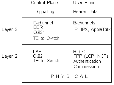
Everything that is important occurs in the Control Plane on the D-Channel.
The ISDN connection reference points are represented by the following diagram:

Rate Reference Point (R)
Older equipment may have a Terminal Equipment Type 2 (TE2) interface presented on X.21 or V.35. Such an interface
requires a Terminal Adapter and the R reference point refers to the link between the TE2 and the TA.
Terminal Reference Point (T) and System Reference Point (S)
Native ISDN terminals use a Terminal Equipment Type 1 (TE1) interface and use 4-wire
twisted copper to link to the Network Termination Type 1 (NT1). The NT1 is provided
by the service provider in Europe, whereas in the US the customer normally
provides this in the form of a DSU/CSU. These 4 wires can
provide a multipoint bus on which up to 8 devices can be connected (although not using the
ISDN concurrently!).
The S/T reference point is the user-network reference point. You can get networks
in the US where the S and T are separated.
The S reference point sits between the TE1/TA and the NT2. The T reference
point is the point between
the customer site switching equipment (NT2) and the local loop termination (NT1).
Routers with 'U' interfaces are expecting to connect to a customer provided DSU/CSU,
and these interfaces should be used in the US. Routers with 'S/T' interfaces are ready
to connect straight into the Exchange line.
The S/T interface caters for point-to-point or point-to-multipoint (8 maximum) on a passive
bus (for BRI only, PRI is only point-to-point). The interface specification is defined by CCITT I.430.
User Reference Point (U)
The U reference point is the
two-wire link between the NT1 and the Line Termination (LT) (or Local Exchange, LE)
which handles the termination of the local loop. Between
the LTs there are Exchange Terminations (ET), and the LT/ETs use SS7 signalling,
the Q.921 signalling is used
only at the local loop.
The 'U' interface is defined by either CCITT ITU I.431 or ANSI T1.601 depending on the country
that you are in.
The V reference point is that between remote terminations.
Routers with a built in BRI or PRI implement TA and NT2 functionality otherwise the router acts as a TE2 and
requires a TA.
The pinouts for the RJ45 (ISO 8877) are as follows:
| Pin |
Wire Colour |
TE function |
NT function |
| 1 |
Green |
Power Source 3 (+) |
Power Sink 3 (+) |
| 2 |
Green/White |
Power Source 3 (-) |
Power Sink 3 (-) |
| 3 |
Orange/White |
Transmit (+) |
Receive (+) |
| 4 |
Blue/White |
Receive (+) |
Transmit (+) |
| 5 |
Blue |
Receive (-) |
Transmit (-) |
| 6 |
Orange |
Transmit (-) |
Receive (-) |
| 7 |
Brown |
Power Sink 2 (-) |
Power Source 2 (-) |
| 8 |
Brown/White |
Power Sink 2 (+) |
Power Source 2 (+) |
The pins are numbered left to right as you look at the socket with the pin at the bottom.
The polarity of the transmit and receive lines indicate the polarity of the framing pulses according to
the Alternate Mark Inversion (AMI) electrical specification.
ISDN uses Time Division Multiplexing to divide the two-wire telephone cable into B (Bearer) channels at
64Kb/s (56Kb/s) and a D (Delta) channel. Basic Rate Interface (BRI) has two B channels and one D channel
whilst Primary Rate Interface (PRI) has either 30 B channels and 1 D channel (MCE1 - UK) or 23 B channels
and 1 D channel (MCT1 - USA).
The bandwidth use can be broken down as follows:
- BRI - B-channels x 2 (64kbps x 2 = 128kbps) + D-channel (16kbps) + framing (48kbps) = 192kbps.
- PRI (T1) - B-channels x 23 (64kbps x 23 = 1,472kbps) + D-channel (64kbps) + framing (8kbps) = 1,544kbps.
- PRI (E1) - B-channels x 30 (64kbps x 30 = 1,920kbps) + D-channel (64kbps) + framing (64kbps) = 2,048kbps.
(Refer to Transmission for more information on T1 and E1 structure.)
In Europe, the Port Application Mode is normally DIALUP 2B+D and the switch
type BRI NET3 for Basic Rate and PRI NET5 for Primary Rate. The term H0 is given
to a group of 6 B-channels. A T1 PRI will have 3 x H0s (because there are only 23 B-channels in T1)
and an E1 PRI will have 5 x H0s.
The B-channel can be used for PCM voice, circuit switched networks such as Frame Relay and X.25
and packet switched networks such as HDLC and PPP. The D-channel is the signalling channel
and is used for call setup and control and can also be used for packet switched networks
like X.25.
The framing for the B-channel is defined by ITU I.430.
The ISDN frame is a 48 bit frame and operates at a speed of 4000 frames/sec. For Basic rate this makes 192 Kb/s data speed and is made
up of 2 x 64Kb/s B-channels, 1 x 16Kb/s D-channel and 48Kb/s of overhead within the BRI frame.
The overhead is the framing and synchronisation bits.

The bits in the BRI frame are described below:
- F, FA, N - Synchronisation bits that use line code violations
- L - DC line balancing
- B1, B2 - Bearer 1 and Bearer 2 channels containing the data
- E, S, M - Collision Avoidance bits, although 8 devices with sub-addresses can be daisy-chained on a multipoint bus,
only one device can talk at a time.
- D - Data channel control
- A - Activation indicator
The following steps happen when a BRI activates:
- A TE signals 01111110 (i.e. the HDLC 7E flag)
- The NT sends frames with the A bit set to 0 meaning 'not activated'.
- The TE synchronises on three sets of the line code violations F and FA.
- The NT synchronises on the line code violations F, FA and N and sets the A bit to 1
indicating that layer 1 is up.
Q.921
The signalling protocol defined in ITU-T Q.920 and Q.921 is Link Access Procedure, D-channel (LAPD).
This protocol is concerned only with the terminal to the local switch link.
The frame format is shown below:

- Flag - 0x7E is the binary 01111110 signal used to synchronise
between the transmitter and receiver. This can often be at the end of the frame as well.
- Address - this is made up of the Service Access Point Identifier (SAPI),
the Command/Response bit and the Terminal Endpoint Identfier (TEI).
The EA stands for Extended Address bits.
- Control - this is one byte in length for the Unnumbered format or
two bytes in length for Supervisory or Information formats.
- Information - contains Unnumbered frames or XID frames (containing parameters
such as window and frame sizes) and contains layer 3 Q.931 call control data.
- CRC - Cyclic Redundancy Check.
PPP or HDLC can be used on the B-channels. Q.921 operates only from the switch to the router. The address field
within the LAPD frame contains a Terminal Endpoint Identifier (TEI) which is a locally unique address
which identifies the terminal. The switch dynamically assigns the terminal with an address between 64 and 126.
The address 127 is used for broadcasts. Reloading the router forces the switch to reassign a TEI.
The Service Access Point Identifier (SAPI) within the LAPD address defines the message type. SAPI 63
is used by layer 2 management (e.g. address assignment), SAPI 64 is used for call control and SAPI 0 indicates
layer 3 signalling (Q.931).
Just like in HDLC, the control field indicates the type of message being used. The TEI uses an unnumbered information frame
(UI - 0x03) with SAPI 63 and TEI 127. The terminal starts to set up a call using Set Asynchronous Balanced
Mode Extended (SABME) which returns an Unnumbered Acknowledge (UA) if successful or a Disconnect Mode (DM)
if unsuccessful. In the Info field the three states Receiver Ready (RR), Reject (REJ) or Receiver Not
Ready (RNR indicate the state of the data transfer mode.
Q.931
Layer 3 ISDN signalling is specified in Q.930 (ITU-T I.450) and Q.931 (ITU-T I.451) and operate locally
between the router and the switch. Different switch vendors have different bit interpretations hence why the switch
type is important. Like Q.921, Q.931 is only concerned with the terminal to local switch, and
it deals with making and tearing down the call. Within the ISDN network itself SS7 Internal Signalling
Utility Protocol (ISUP) is used. The fields for Q.931 are shown below:

The Call Reference Flag is 0 when the frame comes from the call originator and 1 when to the
call originator. The Message Type can use 0x05 for Q.931 setup, 0x45 for disconnect and 0x7D
for status. The Information Element contains the Q.931 parameters such as 0x04 for bearer capability
0x6C for Calling Party Number and 0x70 for Called Party Number.
The Q.931 call setup occurs as follows:
- The TE sends a SETUP message containing information elements detailing the called party, identifier and capability.
Not all service providers send Caller Line Identification (CLI) and sometimes
charge extra for the service. CLI can be used to screen calls by comparing the dialling number
with a table of allowed numbers thereby preventing unwanted calls and giving a little
extra security along with CHAP/PAP.
- The LT/ET responds with a SETUP_ACK.
- The LT/ET passes on the SETUP into the cloud and sends back to the TE a CALL_PROC message with a B-channel
ID number that is to be used.
- Meanwhile, the remote LT/ET sends the SETUP to the remote TE.
- The remote TE responds with a CALL_PROC.
- The remote TE sends an ALERT back through the cloud and this is received by the local TE to indicate that ringing is happening.
- The remote TE is answering when it sends a CONNECT message to the remote LT/ET.
- The remote LT/ET locally sends a CONNECT_ACK to the remote TE and passes the CONNECT through the cloud.
- The local LT/ET sends the CONNECT message to the local TE.
- The local TE sends a CONNECT_ACK to the local switch and the call has successfully completed layer 3 signalling
and is up.
The DISCONNECT message is used to clear the call. The following steps outline the tear
down procedure:
- One station issues a DISCONNECT message to it's local switch.
- Next a RELEASE message is sent from the the station to the local switch.
- The local switch sends a DISCONNECT to the remote switch and on to the remote station.
- The remote station responds with a RELEASED message to the remote switch and this
is passed to the local switch and on to the local station.
- The local station sends a RELEASE_COMPLETE to the local switch and this is passed
on to the remote switch and the remote station, at which point the call has ended.
In the US there is an additional step whereby Service Profile
IDs (SPID) are exchanged and identify specific terminals to specific profiles. The switches DMS-100 and
NI-1 definitely require SPIDs to be configured.
QSIG
'Q' point Signalling (QSIG) is an alternative to using Q.931 and is designed to take into account the
signalling requirements of voice networks i.e. Private Integrated Services Network Exchange (PINX).
It only works on PRI interfaces and povides the ability to carry proprietary PBX features.
The QSIG CCS protocol is significant because it is based on Q.931 and Q.933 and is being developed to cover the first
three layers of the OSI model with layer 3 being the messaging layer. The messaging facilities are more complex allowing
for fetaures such as Call Forwarding, CTI and ACD to be extended across the digital trunks between different
PBX manufacturers.

The standards supported are European Telecommunication Standards Institute (ETSI) standards:
- European Computer Manufacturers Association (ECMA) 141 interexchange Signalling Data Link Protocol.
- ECMA 142 covering the model and information flows for controlling circuit mode services in Private
Telecommunication Networks (PTN).
- ECMA 143 covering QSIG Basic call services.
- ECMA 165 protocol for the support of Supplementary Services
Signalling System 7 (SS7)
SS7 was developed in 1981 to provide out-of-band signalling for establishing calls, routing calls, exchanging
information and billing. Call setup is very fast and traditional PBX facilities such as call forwarding, call transfer
and call screening can be extended across the voice network. Having a dedicated control channel for signalling provides
greater security from fraud and signal interference plus the channel can provide signalling for the whole trunk group.
SS7 is dealt with in more detail within the document SS7.
Dial Services
Within the analogue and digital environment there are three types of Dial services:
- Dial on Demand.
- Dial Backup.
- Bandwidth on Demand.
Before dial circuits can be configured pools must be created. Dial services could be through:
- Dial modems connected to the Public Switched Telephone Network (PSTN).
- CSU/DSU.
- ISDN Terminal Adapters.
- A direct ISDN connection (MCE1 PRI, or BRI modules)
Only one encapsulation type is allowed and the default is HDLC.
Also PPP can be configured on any lines placed in the pool and an authentication protocol such as
Password Authentication Protocol (PAP) or Challenge Handshake Authentication Protocol (CHAP) must also
be configured. A Pool, identified by a Pool ID is a logical group of physical interfaces available for dial up services, an
example is a Demand Pool. More than one pool can be created on one router and an interface can be in more than one pool,
so that an interface could be used for Dial on Demand and be in a Demand Pool and also could be used for Bandwidth
on Demand and be in that particular pool.
With a Dial Backup service, the backup circuit inherits the protocols of the primary circuit when the primary goes down.
Once the primary comes back up, the secondary is taken down. One router is always configured as the master (which
initiates the call) and the other as a slave, this saves a busy line being detected as both routers try and call
each other at the same time. Detection of primary circuit failure depends on the circuit type;
As an example, in Nortel Networks routers the protocols Bay Networks Standard
and PPP use BOFL (Breath of Life), Frame Relay uses the A-bit (only on Direct mode configuration) and X.25 uses a Call Setup failure.
Connecting mixed vendor routers using PPP Dial Services may not work correctly since CHAP and BOFL may be vendor specific.
A Dial on Demand circuit can be activated when the router sends data, or according to a daily schedule or
you force a dial. Ports in a Demand Pool must be on the same slot and a Demand circuit can only be associated with
one pool although a backup Pool can be configured. In order for the NCP layer of PPP to open the connection
the IP or IPX address of the remote must be known so adjacent hosts are configured to enable this to happen.
Also, in order to prevent the dial-on-demand circuits from remaining permanently up there are ways to keep the circuit
down unless necessary, such as configuring static routes, using RIP triggered updates, extended IPX/RIP and SAP
broadcast timers and traffic filters to block unnecessary traffic.
The PPP Multilink Protocol (MP) allows a number of small bandwidth circuits to be aggregated into larger
ones when traffic is heavy, thereby making cost effective use of dial or ISDN lines and paying for only
what is used. A Multilink circuit is called a Bundle and can contain up to four links, the MP process
adds a header, with a sequence number, to the packet, and sends the packet down the fastest link in the
bundle. Processes such as Wellfleet Compression Protocol (WCP) compresses the packet (if it is enabled), and then the packet is uncompressed at the
other end and resequenced. There are two types of line within a bundle; an Initial Line, used initially
for data transfer; and a Secondary line which comes into play when the initial line becomes congested.
In a point to point link, one of the routers is configured as a Congestion Monitor which measures
percentage utilisation of the links. Thresholds for percentage utilisation and sampling periods can be set
on the router to determine at what stage extra links are brought into the bundle. One thing worth noting is
that the congestion evaluation just looks at the number of bytes going in and coming out of the multilink process
without taking into account compression, so what actually goes out over the links may be over evaluated by 100%
(if the compression ratio was set at 2:1) for instance, so that an extra link is brought in unnecessarily.
V.25bis Call Initiation
An HDLC-like frame is used to control the modem, and if the modem supports ASCII encoding, and it uses the bit
oriented HDLC (NOT the byte oriented BSC frame) then the following commands are issued from the router to the DCE:
| Command |
Description |
| CRNn |
Call Requested Number |
| CIC |
Connect Incoming Call |
The DCE issues the following responses:
| Response |
Description |
| INC |
Incoming Call |
| INV |
Invalid |
| VAL |
Valid |
| CNX |
Connect |
On Call failure the DCE issues the following indications:
| Indication |
Description |
| CFIAB |
Call Failure Indicator Abort |
| CFICB |
Call Failure Indicator Communication Busy |
| CFIET |
Call Failure Indicator Engaged Tone |
| CFIFC |
Call Failure Indicator Forbidden Call |
| CFINT |
Call Failure Indicator No Tone |
| CFIRT |
Call Failure Indicator Ring Tone |
The following need to be configured on the DCE:
- Bit Synchronous V.25bis frames.
- ASCII coding.
- Space Parity.
- Mark Idle, the router sends a stream of 1s when it has nothing to send.
- V.25bis Call Progress Messages, the DCE sends a VAL upon receipt of a CRNn command, and a CNX when the
remote DCE is ready to communicate.
- V.25bis Hardware Signalling.

|
