Building a PC Tutorial
Introduction
This step by step guide shows you how to build a new PC from scratch.
Planning
Before anything else happens you first need to be clear what you are going to use the PC for. This aids you in determining the components
that you need to order. It is no longer the case that the most powerful processor is best. Memory, graphics cards and hard disk
specifications are more important. The hard disk is the slowest component, the modern processors and the graphics cards are fast enough
for any application the average user will require, including games.
List the components:
- Case, either ATX or mini ATX with a least a 300W power supply. The case comes with a set of suitable screws and power lead.
- Monitor
- Keyboard
- Mouse
- Motherboard, commonly this has integrated 3D graphics, 5:1 sound, Local Area Connection and USB 2.0 hub
- Processor (CPU), normally either Athlon Semperon or Intel Pentium IV
- Operating system e.g. Windows XP Home or Linux Desktop.
Tools
- Long Philips screwdriver
- Long electricians flat-bladed screwdriver
- Tweezers (for jumper removal and insertion)
- Thermal compound (used when attaching heat sinks to processor chips and graphics chips)
- A pack of screws, jumpers and standoffs (used to stand the motherboard away from the case)
- A grounded wriststrap to protect the components from electrostatic discharges.
- Small electricians pliers
Step By Step Construction
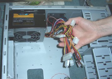
1. Open up the case, normally ATX and mini ATX.


2. Identify Power leads.
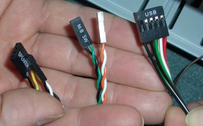
3. Identify front panel leads.
4. Locate the Motherboard.

5. Locate the CPU, observe the missing pins and match these with the socket on the motherboard.

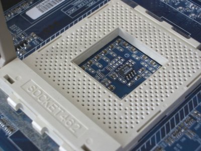
6. Lift the lever of the socket and gently drop the processor into the socket and push down the lever so that it locks in place.
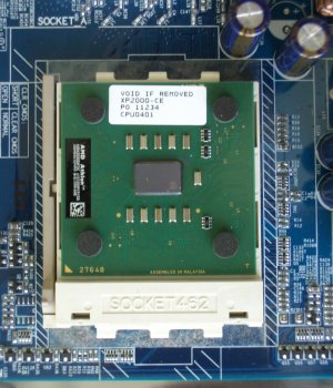
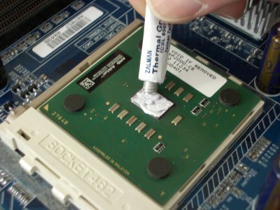
7. Spread thermal grease thinly on to the top of the actual processor casing.
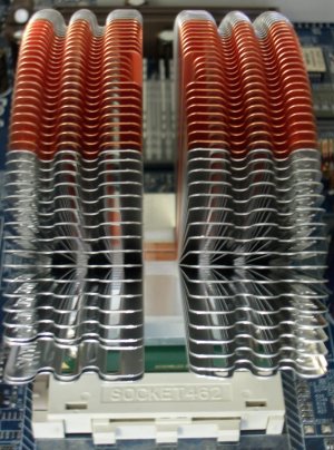
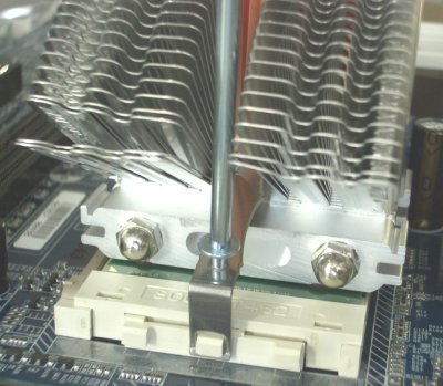
8. Find the cooling device and push the fixing clip through the cooler and clip on the short end onto the processor socket.

9. Use the tool to push the other end of the clip to the other side of the processor socket.
10. If you have an adjustable speed fan for the CPU cooler then the fan should be fitted to
the case after the motherboard has been installed.
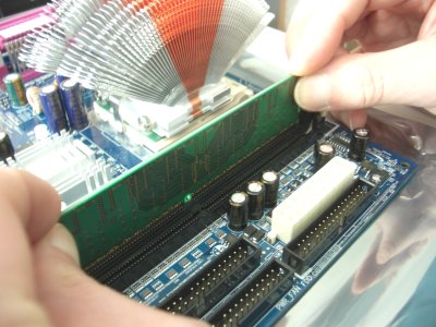
11. Locate the memory chip(s) and insert them into the memory slots starting from the slot DDR1. Push firmly, holding
the memory chips on both sides ensuring that your fingers are not in the way of the side clips that holds the memory in place.
12. If the Case has a former for the motherboard outputs, it is unlikely that this will match the motherboard exactly. So
knock out the former and use the one provided with the motherboard.


13. If the motherboard's former has a panel blocked for a port such as the Ethernet port then just knock out this panel.
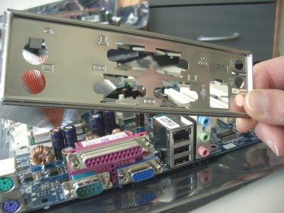
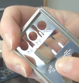
14. Insert the motherboard former.

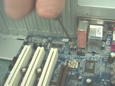
15. Find some standoffs (e.g. metal jack screw standoff #4-40) that raise the motherboard just off the case surface, also some screws
(e.g. #4-40 x 3/16" long) that fit in the spacers to screw
the motherboard to the case.
16. The number of spacers required will be determined by the number of shielded holes in the motherboard.
So position the motherboard to discover where to screw in the standoffs.

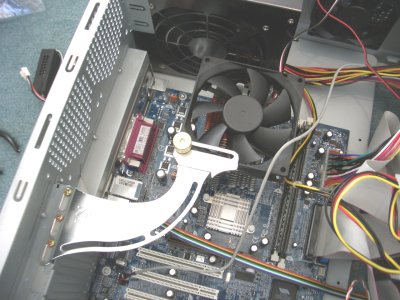
17. Screw the standoffs in the case at the relevant positions and place the motherboard on top ensuring that the ports fit snugly into
the former.
18. Screw the motherboard on to the standoffs.
19. At this point it is a good idea to connect the case connectors. These tend to be located together on the motherboard near the
front of the case.


- Soft power switch (motherboard power switch). It does not matter which way around this is connected
- Reset switch, again it does not matter which way around this is connected
- LED hard disk indicator (sometimes called power LED).
- Sleep message indicator (if the case supports this)
- Internal speaker connection
The order in which these are connected will depend on which is easiest physically. Normally top left to bottom right is easiest.
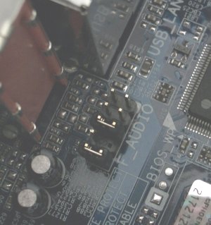
20. If you have a front audio panel then remove any jumpers that are installed on the motherboard connector and connect the
front audio panel lead. Normally there will be a blank pin so that there is only one way of connecting the lead.


21. Similarly, locate the front panel USB connector(s) (these are additions to the rear USB connectors) and connect the USB lead(s).
There is usually only one way in which these can be connected.

22. Decide where you want to install the various drives. Normally there would be a 3 1/2 inch floppy drive, a DVD drive and a hard disk.
23. Remove the front plastic cover. There are normally cleats that can be squeezed by hand to release the front cover from the
metal chassis.
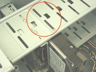
24. Remove any metal barriers that are in the way between the drive and the front cover. Normally these are loosely moulded to the
metal interior and can be removed by judiscious wiggling until the barrier snaps off.
25. Check the jumper on the DVD drive to ensure that it is set as Master. This will be the first drive on one of the Extended
IDE (E-IDE) channels.
26. Insert the DVD drive and floppy drive in through the front of the case.
Some cases will have their own fascias that sit in front of the drives.
27. Install the plastic front cover back on to the chassis.
28. A button on the fascia impinges on the drive button
to transfer the action when operating of the drive. Use suitable fixing screws for each drive, normally 4 per drive to
fix the drive into the cages built into the case. Ensure that the drives are flush up against the front of the case
so that there is good positive action when using the buttons on the front of the case.
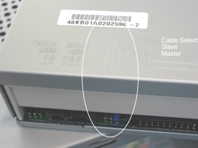
29. Install the hard disk. Check the jumper. If this drive is the master (first hard disk with the bootable operating system)
then the jumper should be set to master or Cable Select (CS). If the jumper is set to CS then the first connector on the
Extended IDE ribbon cable must be used for this drive. When installing the drive ensure that two screw holes can be used on each side
to attach the drive to the chassis.


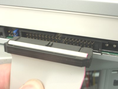
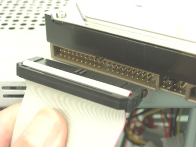
30. Connect an extended IDE cable to the DVD ROM drive. The blue end connects to the motherboard and the red strip connects to the
right handside at the back of the drive. Blips in the plastic suround help you get the cable connected the right way round. Check
the jumper of the drive. This should be set to master if it is the first drive on this IDE bus. The optical drives and the hard disks
must be installed on separate IDE buses. When installing the IDE cable to the motherboard you may need to support the motherboard
with your fingers to avoid bending it too much.

31. Untangle the power leads with the various connectors and select the leads which do not contain the small floppy disk power lead.
32. Install one of these power leads into the DVD drive.

33. Locate the DVD ROM audio lead and connect this to the DVD drive.

34. Find the location on the motherboard for the DVD audio lead and connect it.

35. Connect the floppy drive IDE cable. The twist goes at the floppy drive end and the red stripe (pin 1) goes to the left at the back
of the floppy drive. There is normally a blip in the plastic surround that corresponds with a gap on the motherboard and floppy drive
connections.


36. The small floppy power cable is installed next. There is only one way round that this can be installed too.

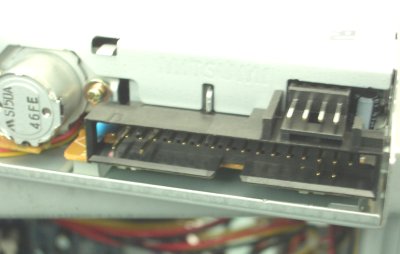
37. Install the Extended IDE cable for the hard disk. The blue end connects to the motherboard and the red strip connects to the
right handside at the back of the hard disk. Blips in the plastic suround help you get the cable connected the right way round.
38. Connect the motherboard power lead.
39. Connect the case fan if you have one. You may need a four-to-three pin power adapter.
40. Install the CPU and graphics chip fan assembly. You may need to remove screws or retainers that hold the slot blanks in place.


41. Connect up the variable speed device and the CPU fan to the motherboard.


42. Ensure screws are used to hold in the PCI slot blanking plates.
43. Put the case back together and connect the keyboard, mouse, screen, speakers and LAN connections.
Software Installation

1. Switch on the computer and when prompted insert the Windows XP CD and press 'Enter' to boot to the CD for XP installation,
following the onscreen instructions through to completion.
2. Update the latest bug fixes from Microsoft's update site. To do this click on the 'Windows Update' icon and follow the instructions.
3. Stick the license number sticker on the side of the PC for future reference.
4. Next, install drivers and motherboard hardware monitoring software from the motherboard CD.
5. Often virus checker and firewalling software is included with the motherboard. Install, sign up and update these packages.
6. The PC is now ready to install any other software that you wish to run on it. Some recommended suggestions are as follows:
- AVG version 7.5 antivirus (includes a scheduler, virus guard and email checker)
- Free Anti Vir. Does a similar job to AVG
- Lavasoft's Adaware to block and remove spyware
- Spybot's Search and Destroy
- Agnitum's Outpost firewall
- Google's toolbar with popup blocker
- Winzip
- Adobe Reader

|
