Cabling Terminology and Standards
Introduction
This document puts into perspective the various terms and standards associated with structured cabling.
It is not conclusive and will evolve as the standards gain additions and new terminologies emerge. As you will
see, some of the terms have yet to be explained and are presently listed as a reminder that they exist and have
some importance.
Terminology
Decibels
The Intensity (I) of any kind of travelling wave, be it sound, light, water etc.
is given by the formula:
I = 1/2.pw2x02u
Where I is measured in watts/m2, p is the density (kg/m3)of the medium in which
the wave is travelling, w is given by 2n/T where n is pi and T is the period of
oscillation for a Simple Harmonic wave. In addition, x0 is the amplitude
of the wave (m) and u its velocity (m/s).
w is also given by 2nf where f is the frequency of the wave. w is called
the angular frequency of the wave.
For the case of sound waves, the smallest sound intensity (I0), detectable by the human ear is
approximately 10-12 W/m2. A tube train is 1010I0, whereas
a jet aircraft is 1015I0.
So, if I = 1015I0
Then, I/I0 = 1015
The increase in 'loudness' of a sound is dependent upon the ratio of the intensities rather than the
absolute differences in intensity. The increase in loudness is calculated by taking the logarithm
of the ratio of the intensities to base 10 and this is measured in bels. So from the above equation:
The noise of a jet aircraft expressed in bels is given by log10 (I/I0) =
log10 1015
Using the laws of logarithms this gives 15log10 10 = 15 bels
Normally working in bels is a bit cumbersome so the standard way of working is to use
decibels which is one tenth of a bel. So the noise of a jet aircraft is about
150 decibels, given by 10log10 (Ij /I0) relative
to the lowest intensity of sound that a human ear can detect.
For an example, if the volume of a Hi-Fi system is turned down such that such that the power
decreases from 1000mW to 200mW then the change in power, in decibels is given by:
10log10(200/1000) = 10log102 - 10log1010 = -7dB
The minus sign indicating a decrease in power.
So when one states that there has been a loss of x dB across a connector or a circuit,
this means that there has been a decline in intensity of a given signal as indicated by
the ratio x.
In the structured cabling world decibels are used as a measurement of noise, attenuation, and signal loss.
Length
The length measurement is achieved using Time Domain Reflectometry (TDR) techniques, a pulse is sent down the line
and the time that it takes to receive the pulse back at the tester transmissions device is used to determine the length of
the cable. Different type of cable will produce different results therefore a secondary parameter is necessary that
distinguishes the type of cable being tested. This parameter is referred to as the Nominal Velocity of Propagation (NVP)
and is expressed as a percentage of the speed of light (c.). Typical values for Category 5 cables range from 0.65c. to 0.85c.
If the incorrect NVP is entered into the tester the results can be totally misleading where a 91 m link appears to pass the
test whereas the true reading may be a failing 105 m link.
Cancellers
Unbalanced and Balanced Transmission
An unbalanced circuit has one of the wires in a pair grounded at both ends. An example
is EIA-232. The problem with this is that any noise produced from external sources
such as voltage switching, balast from flourescent lights etc. will add to the signal
and be seen as data. This is because any noise appearing on the ground wire is sunk
to earth whilst still adding or detracting to the signal in the signal wire. This gets worst
at higher data rates and over longer distances. Using a shield ground at both ends helps
to alleviate the problem
A much better way to resolve this issue is to use a balanced circuit. A balun, a small
transformer, isolates the wires from the circuitry and instead of passing a 0v to 2v signal,
for instance, it passes a -1v to +1v signal such that each wire passes the opposite signal of the
other wire's signal. In theory, the resultant EMF should be zero. The better quality of the
cabling system components the more likely the signal fields cancel each other out. As the signals travel
the wire the same amount of noise is picked up by both wires resulting in their being zero difference
between the signals at the recieving end.
There are considered to be two types of transmission in a balanced cable:
- Differential Mode, where the conductors in a pair carry the same signal but opposite
in polarity. The assumption is made that the transmission line is infinitely long and is perfectly
uniform and that there is zero radiation.
- Longitudinal Mode, where the sent signal is not perfectly balanced and the twisted
pair is not perfectly balanced. This results in the two signals on the conductor not completely
cancelling so that a net current is induced on the pair thus producing radiation. EMF from surrounding systems
is coupled onto the pair.
Installation imperfections mean that some of the differential signals convert into longitudinal
signals (Longitudinal Conversion Loss so both differential and longitudinal modes need
to be examined when looking at EMC and crosstalk (Differential Mode NEXT). This loss is
called the balance of a cable and is measured at one interface, typically the transmitter end since
this is where much of the EMC is likely to occur. There is another measurement called Longitudinal
Conversion Transfer Loss which is measured between the two interfaces at the ends of
a link and so takes into account the differential noise at the receiver.
Common Mode means that a current flows down both conductors in the same direction and uses the
earth as the return path. Common mode noise current is often 'shunted' to earth via an earthed
centre tap on the receiver transformer.
Attenuation
Attenuation is where the signal is diminished due to losses incurred throughout the transmission medium
be it fibre or copper. For copper, it is normally measured in decibels per 100m, meaning the ratio of intensities
between the far end of the 100m and the starting end for a given signal, a ratio of power out over power in.
In copper, attenuation is largely due to copper loss and to dielectric loss from
the jacket materials used around the wires. Polyethylene and Teflon are currently the best materials that
minimise dielectric loss, or dissapation. Attenuation over a certain length of cable is linear for a given
frequency but is different for different frequencies and temperatures.
Attenuation in fibre is far less than that for copper. Lucent Technologies guarantee that for
multimode fibre there is a loss of 3.4dB/km at 850nm, whilst for singlemode Truewave fibre
the loss is 0.22dB/km at 1550nm.
Attenuation (dB) of a cable or connector, is given by
10.log (received signal power without cable/received signal power with cable).
How to measure parameters such as attenuation, NEXT and Structural Return Loss is defined in ASTM D 4566.
Insertion Loss
The maximum insertion loss allowed for a 10BASE-T link is 11.5dB at all frequencies between 5.0 and 10.0 Mhz.
This includes the attenuation of the cables, connectors, patch panels, and reflection losses due to impedance
mismatches to the link segment.
Nominal Velocity of Propagation (NVP)
In a conductor, electrons travel at near the speed of light. For a copper cable this
speed is often expressed relative to the speed of light. For Lucent's 3071 cable
the NVP is given as 0.69, meaning that electrons are travelling at 69% the speed
of light. The lower the NVP, the greater the delay in signals reaching a destination, so a
high NVP is required for a good quality cable.
The NVP of a particular type of cable can vary between batches. This variation can
be as much as 20% so if cable testing is carried out then it is important to
implement NVP calibration of each batch and adjust the default NVP value (built in to the
tester) to the measured NVP for the particular batch. NVP calibration involves
using the tester to measure a known length of cable and adjusting the tester's
length measurement accordingly.
Wire Map
The wire map test is crucial on UTP/STP systems as if this fails then it is likely
that most applications will not even begin to work. The wire map test is simply
a check to see that wires are connected one-to-one at each end.
As well as shorts and open circuits, reversed pairs, crossed wires and split pairs
are detected.
Capacitance
A capacitor is a device that stores electricity and it consists of two metal conductors surrounded
by a dielectric. When there is a circuit attached to the conductors (such as used by
a carrier signal down two wires) a potential difference exists across the two conductors. Whilst this
potential difference exists, electrons flow within the circuit to the conductor on the most negative side
of the circuit whilst electrons also flow away from the most positive side. This happens until
the potential difference across the conductors exactly counteracts that of the attached circuit.
If the circuit is disconnected then the two conductors maintain the potential difference
until they are connected together. Once this happens a current flows for a short period of
time as the electrons flow in order to bring back a zero potential difference between
the conductors. This is called discharging.
Capacitance is measured in Farads and is given by Q/V, where Q is charge
(measured in coulombs) and V is the potential difference (measured in volts).
Because a farad is a very large unit of measurement you will more commonly see microfarads
(10-6) or picofarads (10-12).
The Mutual Capacitance of a cable is that which exists between the two conductors of
a pair. The higher this is, the more likely the possibility of there being interference
between the wires. EIA/TIA 568A sets an upper limit of 5.6nF/100m of Category 5 cable.
Characteristic Impedance
Being the AC equivalent of DC resistance,
impedance of a data circuit takes into account not only the resistance of the copper wire
but also the reactance of the cable capacitance. For an alternating current the instantaneous
voltage is given by:
I0R.sinwt - XCI0coswt
XC is the reactance of the capacitor and the voltage across the capacitance lags
that across the resistance (R) by 90o.
By use of trigonometry (and without going into details) we end up with the impedance
of a data circuit being given by:
Z = V/I = (XC2 + R2)1/2
We can complicate matters by also including the reactance of the inductance of a cable in the maths
since strictly this also makes up impedance, however to simplify matters we won't.
The Input Impedance is the impedance of a particular circuit or cable at a
specific frequency.
The characteristic impedance of a cable is the specified and manufactured impedance
for that cable. This value is obtained by taking plotting the input impedances for each
frequency over a range and applying a smoothing function to the curve.
The Characteristic Impedance should remain constant throughout the length of the cable, however
variations from this characteristic impedance will be due to faults
within the cable or the connecting hardware. Time Domain Reflectometry is used to find impedance defects.
Category 5 cable is designed to have a characteristic
impedance of 100ohms. The specifications require the impedance to not deviate from 100ohms
by more than +/- 15 ohms for each frequency from 1MHz up. All components within a cable
link should match each other at each frequency since an impedance mismatch will hinder
coupling of the signal from one component to another and result in reflections and ateenuation.
Standards such as IEC 1156 and ATM D-4566 define impedance measurement on long cables.
Coupling Attenuation
Resistance Unbalance
(See EIA/TIA 568A section 10.2.4.2)
DC Loop Resistance
This is the resistance of the wire pair when short-circuited at the far end. This is important
for Token Ring that uses relays to allow in and shut out stations from the Multi-station Access
Unit.
Attenuation Deviation
Pair to Pair Near End Cross Talk (Pr-Pr NEXT)
Crosstalk is defined as signals that have been induced, or coupled, from one active pair of wires (disturber),
to another. The name comes from the effect occurring within multipair telephone cables
such that other people's conversations could be heard on the line that you yourself
were using. The current from the one pair of wires was inducing an emf within an adjacent
pair of wires.
Pair to pair Near End Crosstalk describes the noise from the transmit pair
coupled onto the receive pair of wires within the same jacket
and at the near end, meaning as applied to the receive pair nearest to the transmit end.
In a four pair cable, if one pair is used for transmitting a signal, then some noise will be induced
on to the other pairs to varying degrees. Cable balance, twist rates and cable spacing are all factors
that help reduce crosstalk. There are also crosstalk cancellation methods available.
NEXT is measured in decibels, and is the difference in amplitude between the actual
signal and the crosstalk signal. The NEXT effect is often expressed
as crosstalk isolation or NEXT Loss, meaning that the higher the crosstalk isolation
the less the coupling effect. NEXT is effectively a measure of the attenuation
between pairs, therefore, a high NEXT Loss is good!
The crosstalk signal is strongest at the transmit end of the pair and the next 20m. For this
reason the socket at the far end is excluded from NEXT calculations as it has minimal impact. The
NEXT is calculated by antilogging each noise component and then summing the noise (measured in mV)
before logging the sum. To verify the Channel quality, EIA/TIA 568A recommends testing both
at the frame end and at the socket end since the far end is not included in the test itself. When
this has been carried out, then you will see two sets of results, one for the near end and one for the
remote end. Some testers allow this to be carried out without having to swap the tester and the
remote module around.
The tighter the twists within a cable the less chance the pairs have of sharing space with other
pairs and thereby incurring coupled noise. Having different twist ratios per pair results in each pair
having a different lay length (the distance between full twists), the aim being to minimise, as far as
possible, the distance that conductors lie next to each other.
Power Sum Near End Cross Talk (PS-NEXT)
This is the crosstalk between one pair and the combination of all the other pairs within the same
jacket. This is important as more and more applications use all pairs within a jacket (e.g. Gigabit
Ethernet). Power summation is not limited to 4 pair cables, it has been used in the production
of larger pair count cables such as Lucent's 25pr 1061C cable.
Far End Cross Talk (FEXT)
FEXT is the coupling of the transmit signals on to the receive pair or wires at the far end,
away from the transmission source on the disturbing pair.
Expressed in dB, it is described as the ratio of the power induced (Pi) over the power of the original signal
(Po). FEXT = 10log Pi /Po.
The higher the FEXT isolation in decibels, the less the coupling
effect. FEXT is particularly important for data systems that use parallel transmission such as Gigabit
Ethernet (802.3ab) that uses dual duplex PAM-5. NEXT and Delay can be minimised with electronics, but
this is not possible with FEXT.
Power Sum Far End Cross Talk (PS-FEXT)
This is the powersum equivalent of FEXT.
Equal Level Far End Cross Talk (ELFEXT)
Measured in decibels, this is the ratio of the desired receive signal strength to the strength of the noise
induced by the transmit signal at the other end. This is the same as FEXT - Attenuation. The effect of attenuation
on the original signal has been added to give a more realistic result.
Channel Equal Level Far End Cross Talk (Channel ELFEXT)
ELFEXT is most significant for cable, however, in the proposed Category 6 standard Channel ELFEXT
will be important as this includes the FEXT of the connectors.
Power Sum EL Far End Cross Talk (PS-ELFEXT)
This is the Powersum extension of ELFEXT and is calculated by summing the antilog of the
ELFEXT for each pair, and logging the sum.
De-embedded NEXT
Terminated Open Circuit (TOC)
Pair to Pair Attenuation to Cross Talk Ratio (ACR)
ACR is measured in decibels and is equal to NEXT Loss - Attenuation and is a common
method of specifying a cable's performance. ACR is calculated for each pair
and for each frequency measured. For Class D operation the ACR must be 4dB at 100MHz.
ACR gives some latitude when looking at a cable's performance in a cabling system which
has a large variety of lengths. A short length is likely to have relatively poor crosstalk
loss but low attenuation, whereas a long length will have relatively good crosstalk loss
and high signal attenuation.
ACR is a very important measure of how well an installation carries data. At a frequency
of 200MHz you should be looking at a good 6dB difference between the Attenuation and Crosstalk
curves indicating a 75/25 Signal/Noise ratio. Compare this with a 4 dB difference giving
a 50/50 Signal/Noise ratio.
Often, margin values, in decibels, are quoted for ACR measurements. These express
how far away the ACR value is from the limits imposed by the particular
standard being measured against. A positive value indicates that the ACR value
is above the standard and is therefore OK.
Power Sum Attenuation to Cross Talk Ratio (PS-ACR)
Alien Near End Cross Talk
This is the noise induced on a cable by another cable running parallel to it, whether
signals are being transmitted or being received. The more cables that there are
within a bundle the more mixed is the induced noise. Even adjacent bundles will add
to the effect.
As stated earlier crosstalk effects are most prevalent closest to the transmit end. To this
end it is important to make sure that the cable bundles leaving the patch frames are not all
running in parallel to each other. This includes the bundles sitting in trays and loose
laid on the floor.
It is also important to make sure that the cable management
allows the patch leads to be loose laid and not be running tightly together in parallel. This
loose laying of patch leads is important as it helps to attenuate the crosstalk before it enters
the cable bundles. Provided that you keep to patch lead length guidelines, the longer the patch lead the better
as this gives more chance for the alien crosstalk to attenuate.
Bends and tight cable ties affects the balance of the cable and therefore makes it more susceptible
to noise as the cable is more likely to radiate noise and also receive noise.
Pre-bundled cables need to be balanced with each other before being installed on site.
Channel Propagation Delay
Measured in nanoseconds, this is the time required for a signal to travel the whole channel.
Quantifying delay is important
as protocols such as Ethernet rely on the time it takes for frames to traverse a LAN. With CSMA/CD,
if there is a collision, the circuitry of the sender waits a certain amount of time before
resending. This amount of time is the time it takes the signal to travel 205m of UTP (100m there
and back plus 5m). This is called the Collision Domain Parameter. A cable that has
low delay characteristics is ideal for faster protocols.
The new standards are looking at this being at a maximum of 535ns over 100m. TSB 67 does not
define a limit, but ISO/IEC 11801 has an upper limit of 1us.
Propagation Delay Skew
Also measured in nanoseconds, parallel transmission protocols (e.g. Gigabit Ethernet, 100BaseVG
and 100BaseT4) use more than one pair to transmit signals. Delay Skew
is a measure of the difference in delay between two signals travelling down separate pairs.
Because the number of twists are different for each pair, the length of each pair is slightly
different for each cable. Other names for this are Asymmetric Skew or Differential Delay.
A good quality cable will have a tightly controlled NVP per pair and the electronics associated
with the particular parallel transmission technology such as Gigabit Ethernet, will be able
to cope with the Delay skew provided that it falls below the limit.
The new standards are looking at this being 45ns as a maximum allowable value. The current agreement
after TSB 67, is 50ns as an upper limit.
Structural Return Loss
A fibre or a wire will have imperfections and variations in density that cause some of the energy
to be reflected back. This is called Structural Return Loss. SRL is measured in decibels for specific
frequencies and comes from the Reflection
Coefficient which is the ratio of the incident to the reflected signal amplitudes. A high dB value indicates
lower reflected energy. A good indication of a quality cable is when the noise from reflections is
less than a tenth that of noise from crosstalk. A high value is good!
SRL is important in bi-directional transmission schemes since the reflected signal must not so high
as to make detection of the receive signal difficult.
Channel Return Loss
This tells you something of the quality of the whole network link or channel. Return Loss
is the sum of all the reflected signals from patch panel, connectors and cable arriving back at
the signal originating end.
This will vary across the frequency range 1 to 250MHz and is only significant for the
higher speed data rates. Impedance matching of the components is critical in order to minimise
return loss.
LAN components struggle with reflected energies greater than 20% (7dB). Current standards call for
3% to 10% reflected energies (15 to 10dB).
(See ISO/IEC 11801 section A.1.1.4 for detail on the measurement of Return Loss and Propagation Delay)
Cable Capacity
Cable Capacity (C)(bps) is given by the formula C = W.log2(1 + SNR) where W is
bandwidth (Hz) and SNR is Signal to Noise Ratio (dB).
If the ACR goes to zero at freqency f and Af is the attenuation at that frequency
then in the data cabling world where NEXT is important C = f(0.11(-Af ) - 2.16).
The new Class D channel is to have a pair capacity of 480Mb/s, whilst the proposed class E is to have
1092Mb/s.
Echo Cancellation
Refractive Index
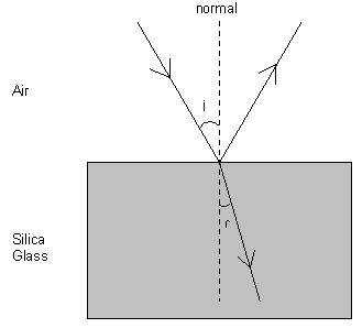
In the above diagram, a ray of light travelling in air, in one plane, hits the glass surface (incident)
at an angle i to the normal. It then changes direction as it travels through the glass
at an angle r to the normal. It is refracted.
The laws of refraction are:
- The incident and refracted rays, and the normal at the point of incidence, all lie in the same plane.
- For two given media, sin i/sin r is a constant, where i is the angle of incidence
and r is the angle of refraction.
The second law is Snell's Law and defines the refractive index for light travelling
from one medium (1) to another (2), this is denoted by 1n2.
The absolute refractive index is defined as the value obtained when light is travelling
from a vacuum to a particular medium. In this case the refractive index is denoted by n.
For glass n = 1.5, for water n = 1.33 and for air n = 1.00028.
Let's look at the trigonometry a little more closely.
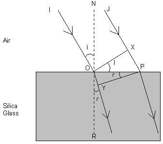
Two parallel rays of light, IO and JP hit the glass surface in the same plane.
Now IO hits the surface as the ray JP reaches point X. If we say
that the distance XP takes t seconds for the light to travel, then since
c is the velocity of light in air, XP = ct. Similarly, if v is the velocity
of light in glass, then OY = vt.
Now, sin i/sin r = sin ION/sin YOR.
Using the other parallel ray of light, sin i/sin r = sin XOP/sin OPY.
Because the sine of an angle = length of the opposite side / length of the hypoteneuse
sin XOP/sin OPY = XP/OP / OY/OP = XP/OY = ct/vt = c/v
This shows that the absolute refractive index of a medium can be calculated from the following:
n = velocity of light in a vacuum / velocity of light in the medium
Now that we have established that light is refracted when travelling from one type of medium to
another, let us look at the special case of light travelling from a medium of higher refractive
index to a medium of lower refractive index.

There is a critical angle of incidence beyond which all the light is reflected back into the first medium,
in this case the glass.
We know that n = sin i/sin r, so for the special case where i is the
critical angle c when r = 90o and n is the refractive index
of the first medium, then:
n = sin c/sin 90o, since sin 90o = 1
From this, sin c = 1/n
The critical angle for glass to air is given by sin c = 1/1.51 = 0.667, therefore c = 41.5o.
In an optical fibre, the cladding has a refractive index which is less than that of the core material and
this provides the right environment for light to continuously reflect its way down the core
of the fibre with minimal loss. For multimode fibre the critical angle is 74o whilst for
single-mode fibre it is 83o. The Cone of Acceptance is the cone produced when spinning
the critical angle about the longitudinal axis of the fibre core. Provided the light rays enter
the fibre at an angle N, which is greater than the critical angle (relative to the horizontal
surface of the fibre end), then the light will successfully be transmitted. This Cone of Acceptance
is often called the Numerical Aperture and is equal to sin N.

Multi Mode Fibre
Multimode fibre either has a 62.5um (American) core or a 50um (European) core, with a 125um
cladding. The cladding is of a different refractive index such that the LED light
source is reflected back to within the core and kept that way until it reaches its destination.
50/125 uses a refractive index of 1.488 whilst 62.5/125 uses 1.499.
The light source can enter the fibre at a number of different angles, or transmission modes.
These angles can vary between
being parallel to the longitudinal axis to close to the critical angle.
Although certain applications such as 10BaseFx can run up to 2km on multimode, data speeds
of 2.5Gb/s can only run up to 300m.
Single Mode Fibre
The core size is much smaller at 8.3um and only one angle (mode) is used. The narrow
beam that is required means that a laser is used instead of an LED for the light source. The
refractive index used is 1.468.
Dispersion
In multimode fibre, dispersion is caused by the fact that the light travelling down the
fibre hits the cladding at different angles (modes). Each pulse is reflected at different points
throughout the travel and some are inevitably reflected more often than others and thereby
travel slightly further. This type of dispersion is called Modal Dispersion and occurs
in multi-mode fibre. This is important since pulses could end up getting so out of synch
that the transmission becomes garbage.
One way to minimise modal dispersion is to 'grade' the refractive index of the core material as
high at the axis to low at the
interface between the core and the cladding of the multmode fibre. This grading then tends to focus, or
correct the dispersion since more of the modes reach the end at the same time. These types of fibres
are called Graded Index Fibres and provide more accurate signal transmission compared to
the more traditional Step Index Fibres.
There are significant performance benefits
to be gained by the use of Graded Index fibre. It can support transmission speeds up to 500 Mhz over distances up
to one kilometre, whereas Step Index fibre can only support typical transmission speeds at 10 Mhz over the same distance.
Nowadays the predominant fibre used in premises cabling is Multimode Grade Index and this has resulted in a significant
reduction in price making it more economical than Step Index fibre.
Each Multimode fibre is coated with a polymeric buffer which protects the fibre, making it flexible and easier to handle.
Numbers of these fibres are then combined to make the cables that are used in structured cabling systems.
In singlemode fibre one wavelength (or mode) is used, however the light source is not pure and
is not fully monochromatic. The small number of different frequencies either side of the main
light frequency are not reflected back into within the core and are lost. This is called
Chromatic Dispersion.
A graph of Attenuation against Wavelength will show you that there are troughs where attenuation
is at a minimum. These troughs occur at the infra-red wavelengths of 850nm, 1300nm and 1550nm.
This is why these wavelengths of light are used for transmission.
Matched Clad Single Mode Fibre
This fibre is made up of a germanium doped 8.3um core and a silica cladding. It is optimised for
1310nm light.
Depressed Clad Single Mode Fibre
This is made up of a germanium doped 8.3um core and two layers of silica cladding. The inner
layer is doped with flourine to depress the refractive index compared with the outer
silica clad. It is optimised for 1310nm light.
Dispersion Shifted Single Mode Fibre
This is optimised for 1550nm light.
True Wave Single Mode Fibre
This uses a core of 6um and is designed to be used with DWDM. This fibre allows a small amount
of dispersion over the band used by Erbium Doped Fibre Amplifiers (EDFA). This dispersion
helps to avoid interference between wavelengths (called Four-wave Mixing). This fibre
allows data rates up to 10Gb/s.
All Wave Single Mode Fibre
Designed for use with DWDM systems using many different wavelengths, it also is designed
to prevent water particle ingress which tended to create higher attenuation in the 1400nm
region.
Time Division Multiplexing (TDM)
Dense Wavelength Division Multiplexing (DWDM)
DWDM is a way of transmitting using multiple optical signals operating at different wavelengths
around the 1550nm area. Data is sent in parallel and the amount of data that can be sent is multiplied
by the number of wavelengths used.
Ultimately, DWDM schemes will come about using hundreds of different wavelengths.
Summary of EIA/TIA UTP Categories
EIA/TIA Category 1 and 2
The characteristics for these two Categories of cable are not specified by EIA/TIA, as they are deemed unsuitable
for structured cabling systems because the applications supported are limited to voice or low speed data (i.e. less than
4 Mbit/s). Anixter/UL Level 1 cable is similar in performance to British Telecom CW1308 cable (standard telephone
wiring) and is only suitable for analogue and digital voice applications or low speed serial communications e.g. 56Kbps. Level 2
performance is approximately equivalent to IBM's Type 3 specification and is suitable for some proprietary communications
systems, such as Appletalk, IBM 3270 and IBM 5250 systems operating at 1Mbps.
EIA/TIA Category 3
Category 3 is the lowest performance specification included in the EIA/TIA568 standard. Although specified to 16mhz,
the levels of attenuation and NEXT set for Category 3 UTP are too high for 16 Mbit/s Token Ring operation over 100 metres
of cable. Therefore Category 3 cable is generally only regarded as being suitable for applications up to 10 Mbit/s (i.e.
10BaseT Ethernet).
EIA/TIA Category 4
Cables conforming to Category 4 are sometimes referred to as Extended distance LAN UTP. The levels of attenuation
and NEXT for Category 4 UTP make it suitable for 16 Mbit/s Token Ring operation with lobe lengths up to 100 metres.
EIA/TIA Category 5
Sometimes known as LAN and High Speed Data UTP. Specified up to 100 Mhz it has been designed to support operation
of 100 Mbit/s services, such as TP-PMD (i.e. FDDI over twisted pair).
Structured Cabling Standards
EIA/TIA 568A
The Electronic Industry Association/Telecommunications Industry Association published the
Commercial Building Telecommunicatrion Wiring standard EIA/TIA 568A and this is principally
recognised throughout the US although it is adopted elsewhere in the world.
The committee that issued EIA/TIA 568A is ANSI/EIA/TIA TR-41.8.1 (USA).
Cables allowed, are 4-pair UTP (up to 90m), backbone UTP (up to 800m) and 62.5um
multimode fibre (50um is not supported).
EIA/TIA 568 specifies the use of 4 pair, 24 A.W.G. (0.5mm) UTP cable of Category 3 or higher. Multipair, which is
limited to 25 pair, is not permitted to be used for horizontal installations in EIA/TIA 568 compliant implementations.
STP
As for the backbone cabling, a number of 150 ohm, 2 pair, 22 A.W.G. (0.6mm) STP cables equivalent to IBM Type 1 are
specified.
In addition the following maximum parameters are required:
- Work area - 3m
- Equipment room - 20m
- Horizontal termination - 7m
- Between the horizontal and the backbone - 6m
- MDF - 20m
- IDF - 20m
TSB (Technical Services Bulletin) 36
This standard details the attenuation specification for Category 3, 4 and 5 cables across
the range of frequencies 0.064 - 100MHz (Category 1 and 2 were
not deemed suitable for data transmission). The following table shows the maximum attenuation
allowed (dB) @20o C over 305m.
| Frequency (MHz) |
Cat 3 |
Cat 4 |
Cat 5 |
| 0.064 |
2.8 |
2.3 |
2.2 |
| 0.256 |
4.0 |
3.4 |
3.2 |
| 0.512 |
5.6 |
4.6 |
4.5 |
| 0.772 |
6.8 |
5.7 |
5.5 |
| 1.0 |
7.8 |
6.5 |
6.3 |
| 4.0 |
17 |
13 |
13 |
| 8.0 |
26 |
19 |
18 |
| 10.0 |
30 |
22 |
20 |
| 16.0 |
40 |
27 |
25 |
| 20.0 |
|
31 |
28 |
| 25 |
|
|
32 |
| 31.25 |
|
|
36 |
| 62.5 |
|
|
52 |
| 100 |
|
|
67 |
In addition, TSB 36 looks at the cable crosstalk specification. Below is a table
showing the worst pair to pair NEXT in decibels at 305m.
| Frequency (MHz) |
Cat 3 |
Cat 4 |
Cat 5 |
| 0.510 |
54 |
68 |
74 |
| 0.772 |
43 |
58 |
64 |
| 1.0 |
41 |
56 |
62 |
| 4.0 |
32 |
47 |
53 |
| 8.0 |
28 |
42 |
48 |
| 10.0 |
26 |
41 |
47 |
| 16.0 |
23 |
38 |
44 |
| 20.0 |
|
36 |
42 |
| 25 |
|
|
41 |
| 31.25 |
|
|
40 |
| 62.5 |
|
|
35 |
| 100 |
|
|
32 |
TSB 40
TSB 40(A) came after TSB 36 and is concerned with the connecting hardware. The following
table details the maximum allowed attenuation (dB)
across connecting hardware at a range of frequencies.
| Frequency (MHz) |
Cat 3 |
Cat 4 |
Cat 5 |
| 1.0 |
0.4 |
0.1 |
0.1 |
| 4.0 |
0.4 |
0.1 |
0.1 |
| 8.0 |
0.4 |
0.1 |
0.1 |
| 10.0 |
0.4 |
0.1 |
0.1 |
| 16.0 |
0.4 |
0.2 |
0.2 |
| 20.0 |
|
0.2 |
0.2 |
| 25 |
|
|
0.2 |
| 31.25 |
|
|
0.2 |
| 62.5 |
|
|
0.3 |
| 100 |
|
|
0.4 |
The following table shows the worst pair to pair NEXT (dB) across a range of frequencies
for the hardware:
| Frequency (MHz) |
Cat 3 |
Cat 4 |
Cat 5 |
| 1.0 |
58 |
>65 |
>65 |
| 4.0 |
46 |
58 |
>65 |
| 8.0 |
40 |
52 |
62 |
| 10.0 |
38 |
50 |
60 |
| 16.0 |
34 |
46 |
56 |
| 20.0 |
|
44 |
54 |
| 25 |
|
|
52 |
| 31.25 |
|
|
50 |
| 62.5 |
|
|
44 |
| 100 |
|
|
40 |
Proposed Category 6 and Lucent's Gigaspeed
The following three tables were Lucent's own and show the comparisons made between its
own cable offerings and the Category 5 standard. First of all a comparison of NEXT performance (dB):
| Frequency (MHz) |
Cat 5 |
1061C NEXT |
1061C PSNEXT |
1071A NEXT |
1071A PSNEXT |
| 1 |
62 |
68 |
65 |
72.3 |
70.3 |
| 4 |
53 |
59 |
56 |
63.3 |
61.3 |
| 8 |
48 |
54 |
51 |
58.8 |
56.8 |
| 10 |
47 |
53 |
50 |
57.3 |
55.3 |
| 16 |
44 |
50 |
47 |
54.3 |
52.3 |
| 20 |
42 |
48 |
45 |
52.8 |
50.8 |
| 25 |
41 |
47 |
44 |
51.3 |
49.3 |
| 31.25 |
40 |
45 |
42 |
49.9 |
47.9 |
| 62.5 |
35 |
41 |
39 |
45.4 |
43.4 |
| 100 |
32 |
38 |
35 |
42.3 |
40.3 |
| 200 |
|
|
|
37.8 |
35.8 |
| 300 |
|
|
|
35.2 |
33.2 |
| 400 |
|
|
|
33.3 |
31.3 |
| 550 |
|
|
|
31.2 |
29.2 |
A table follows comparing the channel performance (dB) between the Category 5 standard system and a Gigaspeed system.
| Frequency (MHz) |
Cat 5 |
Gigaspeed NEXT |
Gigaspeed PS-NEXT |
| 1.0 |
60.3 |
72.7 |
70.3 |
| 4.0 |
50.6 |
63.0 |
60.5 |
| 10.0 |
44 |
56.6 |
54.0 |
| 16.0 |
40.6 |
53.2 |
50.6 |
| 20.0 |
39.0 |
51.6 |
49.0 |
| 25.0 |
37.4 |
50.0 |
47.3 |
| 31.25 |
35.7 |
48.4 |
45.7 |
| 62.5 |
30.6 |
43.4 |
40.6 |
| 70 |
29.8 |
42.5 |
39.7 |
| 100 |
27.1 |
39.9 |
37.1 |
| 125 |
|
38.2 |
35.4 |
| 155.5 |
|
36.7 |
33.8 |
| 200 |
|
34.8 |
31.9 |
| 250 |
|
33.1 |
30.2 |
The final table details Gigaspeed's performance in the additional specifications required for the proposed Category 6
standard:
| Frequency (MHz) |
pr-pr ELFEXT |
PS-ELFEXT |
PS-ACR |
Return Loss |
Delay (ns) |
Delay Skew (ns) |
| 1 |
63.2 |
60.2 |
68.3 |
19.0 |
580.0 |
50.0 |
| 4 |
51.2 |
48.2 |
56.6 |
19.0 |
563.0 |
50.0 |
| 10 |
43.2 |
40.2 |
47.7 |
19.0 |
556.8 |
50.0 |
| 16 |
39.1 |
36.1 |
42.5 |
19.0 |
554.5 |
50.0 |
| 20 |
37.2 |
34.2 |
39.9 |
19.0 |
553.6 |
50.0 |
| 25 |
35.3 |
32.3 |
37.2 |
18.0 |
552.8 |
50.0 |
| 31.25 |
33.3 |
30.3 |
34.3 |
17.1 |
552.1 |
50.0 |
| 62.5 |
27.3 |
24.3 |
24.0 |
14.1 |
550.3 |
50.0 |
| 100 |
23.2 |
20.2 |
15.6 |
12.0 |
549.4 |
50.0 |
| 125 |
21.3 |
18.3 |
11.0 |
11.0 |
549.0 |
50.0 |
| 155.52 |
19.4 |
16.4 |
6.2 |
10.1 |
548.7 |
50.0 |
| 175 |
18.4 |
15.4 |
3.4 |
9.6 |
548.6 |
50.0 |
| 200 |
17.2 |
14.2 |
-0.1 |
9.0 |
548.4 |
50.0 |
| 250 |
15.3 |
12.3 |
-5.8 |
8.0 |
548.2 |
50.0 |
TSB 67 Transmission Performance Specifications for Field Testing of UTP Cabling Systems
This is not strictly a standard, it just compliments EIA/TIA 568A. It is due to be
included in EIA/TIA 568B.
This sets out the requirements for testers, test methods and transmission performance of both
the basic link and the channel link for cables and connecting hardware in Category 3, 4 and 5 systems.
In addition, it defines the accuracy levels Level I and Level II.
Level I has a testing accuracy of +/- 1.3dB for Attenuation and +/- 3.4dB for NEXT. Level II
has a testing accuracy of +/- 1.0dB for Attenuation and +/- 1.6dB for NEXT.
The following diagram illustrates the Basic and Channel links:

The Basic link length is 90m plus 2m at each end for leads and then a further 10% to give 103.4m. The tester
will not fail any length up to this. The Channel link length is 90m plus 10m for
all patch leads, fly leads and equipment leads, and another 10% to give 110m. The 10% is to allow
for NVP uncertainty.
The limits are more strict for the Basic Link since there are less components. It is important
to set the tester to the corrct type of link being tested.
The requirement is that the following are tested:
- Wire Map
- Length
- Attenuation
- NEXT at both ends
The testers that can perform to these specifications are:
- Microtest Pentascanner+ 350 / Omniscanner
- Scope Wirescope 100/155
- Wavetek Lan Tech 8155/8350
- Datacom Lancat System 6
- Fluke DSP100, DSP2000 and DSP4000
Most testers allow you to set the parameters to be in accordance with ANSI/EIA/TIA 568A
or ISO 11801 or EN50173. ISO 11801 should take precedence.
Level II-E tester accuracy relaxes a couple of parameters in the Level II specification
in order not to exclude a couple of the tester manufacturers in being able to pass
Powersum compliant cable installations.
Level III (Cat 6)
EIA/TIA 568B
This will include TSB 67.
TSB 72 Centralised Optical Fibre Cabling Guidelines
Guidelines for centralising fibre cross-connects and electronic hardware.
TSB 75 Open Office Cabling Architecture
Guidelines for zone cabling.
T568A/T568B
Addendum 1
Addendum 2
Addendum 3
TSB 95
This is the new Category 5 testing standard. Note that this is not the 'Enhanced Category 5' standard.
It includes ELFEXT and Return Loss testing.
EIA/TIA 569 Commercial Building Standard for Telecommunications Pathways and Spaces
Guidelines for designing closets, equipment rooms, pathways for work areas and horizontal routes.
EIA/TIA 570 Residential and Light commercial Telecommunications Wiring
This replaces EIA/TIA 568 in these less demanding environments.
EIA/TIA 606 Administration Standards for the Telecommunications Infrastructure of Commercial Buildings
Guidelines for labelling and administration of a structured cabling system.
EIA/TIA 607 Commercial Building Grounding and Bonding Requirements for Telecommunications
Guidelines for the distribution of signal ground throughout a building. Also EIA/TIA 758 is linked with this.
PN 3771 Multi-media Building Distribution Standard
PN 3727 UTP systems
This spurns TSB 67, 72 and 75 plus SP (Standards Proposal) 4194 and SP 4195.
SP 4194
Responsible for Addendum 4 which adds to the Category 5 specification:
- Cable Return Loss
- Channel Return Loss
- Basic Link Return Loss
- Cable ELFEXT
- Channel ELFEXT
- Basic Link ELFEXT
- PS-ELFEXT
- Channel Propagation Delay
- Channel Delay Skew
SP 4195
Addendum 5 is the new Category 5e standard which will raise the values of NEXT, ELFEXT, PS-NEXT,
PS-ELFEXT and component FEXT.
PN 2948 Connecting Hardware
PN 3193 Screened Cabling
PN 3523 Fibre Optics
PN 3894
This group is responsible for harmonising with ISO 11801.
ISO/IEC IS 11801
In 1994 the technical committee of the International Electrotechnical Commission (IEC), an organisation operating under
the 'umbrella' of the ISO, issued a standard known as DIS11801 (Draft International Standard). This standard describes
all parts of a structured cabling network and their associated components. This draft standard was ratified in 1995 and
has been issued as International Standard (IS)11801.
IS 11801 is a design standard and has been developed by the International Standards Organisation to define the building
wiring standards. The workgroup is ISO/IEC JTC1 SC WG3.
Cables allowed, are horizontal 4-pair UTP (up to 90m), backbone UTP (up to 500m), Campus links
(up to 2km) and 50um or 62.5um multimode fibre. If fibre is installed in the horizontal, then it too
must only run for 90m!
In addition the following maximum parameters are required:
- For the work areas: Work area lead + Equipment cord + Patch cord must not exceed 10m.
- The patch leads must not exceed 5m.
- For the campus/backbone: patch cords - 20m and equipment cords - 30m.
There can be a transition point somewhere between the outlet and the patch frame. This optional
transition point must not be a patch point and a one to one wiring must be maintained.
One IDF is required for every 1000m2. Outlets can be served from an IDF on floors above
or below it.
The density of outlets must be such that a minimum of two outlets must serve 10m2.
One of the outlets can be fibre and all baluns such as telephone adapters must be external
to the outlet.
The following clauses sit within the standard:
- Clause 4 - Definition of the wiring structure.
- Clause 5 - Implementation approach (cable types, horizontal distances, backbone distances
and components meet clauses 7 and 8).
- Clause 6 - Link performance approach (5 classes of applications, performance requirements for
cabling link and from clause 5).
- Clause 7 - Cable performance.
- Clause 8 - Connecting hardware.
A Channel is the complete link from one piece of equipment to another and includes
the outlet, the patch cord, work area lead, horizontal and riser cables.
The class of application refers to the speed at which the application runs.
The following table details the channel lengths achievable within each class, and the frequencies
associated with each class:
| |
Class A |
Class B |
Class C |
Class D |
| Speed (MHz) |
0.1 |
1 |
16 |
100 |
| Cat 3 |
2km |
200m |
100m |
|
| Cat 4 |
3km |
260m |
150m |
|
| Cat 5 |
3km |
260m |
160m |
100m |
| 150 ohm |
3km |
400m |
250m |
150m |
| Multimode fibre |
|
|
|
2km |
| Single Mode fibre |
|
|
|
3km |
Coming soon, probably this year, is a revision on Class D to include an enhanced Cat 5 standard to cope
with Gigabit Ethernet.
The basic link specification will be higher and there will be limits set for Delay, Differential Delay,
ELFEXT, PS-ELFEXT and PS-NEXT.
Following that, there will be a second edition of ISO 11801 to include specifications for Category 6 and 7.
ISO 14763 Implementation and Operation
This consists of four parts:
- Part 1 - Administration
- Part 2 - Planning and Installation
- Part 3 - Testing of Optical Fibre
- Part 4 - Testing of Copper cables
The performance requirements at 100MHz are detailed in the following table (values in decibels):
| |
Permanent Link |
Basic Link |
Channel |
| Attenuation |
20.6 |
21.9 |
24.3 |
| NEXT |
26.8 |
26.8 |
25.1 |
| ACR |
8.5 |
7.2 |
2.6 |
Fibre testing under ISO 11801
| |
Multimode |
|
Singlemode |
|
| Parameter |
850nm |
1300nm |
1310nm |
1550nm |
| Attenuation (dB/km) |
<3.5 |
<1.0 |
not defined |
not defined |
| Bandwidth (MHz.km) |
>200 |
>500 |
not defined |
not defined |
| Connector Insertion Loss (dB) |
<0.75 |
<0.75 |
<0.75 |
<0.75 |
| Connector Return Loss (dB) |
>20 |
>20 |
>26 |
>26 |
| Splice Loss (dB) |
<0.3 |
<0.3 |
<0.3 |
<0.3 |
The patch leads are not included since the manufacturer's equipment already accounts for the
connector loss.
Optical attenuation must not exceed 11dB between any two pieces of equipment. The following table
gives the total link parameters for attenuation at different wavelengths and different frequencies.
| |
|
Attenuation (dB) |
|
|
|
| Subsystem |
Maximum Link Length (m) |
850nm |
1300nm |
1310nm |
1550nm |
| Horizontal |
100 |
<2.5 |
<2.2 |
<2.2 |
<2.2 |
| Riser |
500 |
<3.9 |
<2.6 |
<2.7 |
<2.7 |
| Campus |
1500 |
<7.4 |
<3.6 |
<3.6 |
<3.6 |
For multi-mode systems a power meter and light source is fine unless troubleshooting
is required and an OTDR (Optical Time Domain Reflectometer) is needed. Single-mode systems
require OTDR traces.
Testing with the light source and the power meter is straightforward and is used
to give a total figure on attenuation across the fibre link. They are first set to
the required wavelength to be tested. Then they are calibrated by plugging the light source
directly into the power meter, using the light
source test lead only and setting the loss reading to 0dB. Calibration must be
carried out each time the units are switched off or test leads are changed. If slightly
different wavelengths are being used from the norm then use tables in BS7718 (Code
of Practice for Fibre Optic Cabling) to correct the results.
An OTDR sends a pulse of laser light down the fibre. Physical changes in the fibre, such
as connectors, breaks, kinks or the end of the run result in some of the light being
reflected back. Knowing the refractive index of the fibre is necessary to determine accurately
the time it takes for the pulse to travel down the fibre.
Following is an example of a typical OTDR trace:

For this trace the marker is at 92m (the beginning
of the trace after the launch lead), and the cursor at 380m (the end
of the channel. The length difference is therefore 380 - 92 = 288m which is the
length from point to point. The OTDR shows the attenuation and any faults. The
attenuation is about 5dB (from -6 to -11 dB on the trace). The OTDR gives these
figures to greater accuracy as you move the marker and cursor.
When designing a fibre infrastructure it is important to calculate the optical power budget using
the connector and cable losses as specified for the components being used in the
installation. The overall budget needs to be checked against the tables above.
ISO PDTR 147653-2
IEC 61935
600MHz
Coupling Attenuation being developed by Cenelec to support the 2nd editions of IS 11801 and EN 50173.
EN 50173
European Standards are guidelines which are a compromise of all world wide published
standards. Specific areas of Europe have requirements particular to them defined in
regional 'norms' and as a consequence Europe has its own standardisation body called
CENELEC. Within the context of 'Europe' it is considered that the European 'norm' is
of higher importance than the International Standard to ensure that the prevalent
technology available in the relevant country is used. Standard EN50173 is the
corresponding standard to IS11801 and covers cabling, components and in addition,
European directives.
The technical committee is CENELEC TC115, and they work in conjunction with ISO/IEC JTC1 SC WG3.
One principal difference of EN 50173 with ISO 11801 is that the maximum Propagation Delay is 0.9us instead
of 1us.
EN 50167
EN 50168
EN 50169
prEN 50174 Recommendations for Installation Practices
Planning and Installation of IT cabling, the European equivalent of EIA/TIA 569. This will
include field testing when it is finished.
ISO/IEC 14763 Implementation and Operation of CPC
Fire Standards
Despite much debate, few manufacturers have quantified the minimum requirements that communications and building
designers should specify in the area of fire safety in cables and cable infrastructures. Cable vendors are now
however offering a variety of cables that offer degrees of protection against the progression of fire along the
cables and toxic fumes that are produced from burning or smouldering cables. Low Smoke Zero Halogen (LSZH)
cables offer the best protection as they conform to a number of standards issued by the USA and Europe, care
must be exercised as some vendors offer LSZH cables but only the outer sheath and not the inner conductor
sheath is fire retardant.
In Europe standard CENELEC HD405 is used and is very similar to IEC332, which again is very similar to BS4066.
Minimum requirements are identified in two standards:
- If flame spread and fire retardant properties only are required for the cables in an installation, IEC332
Part 3 should be specified.
- If an installation requires full LSZH properties then IEC332 Part 3 for flame spread and fire retardancy,
IEC754 Part 2 for acidic gas emissions and IEC1034 for smoke emission should be specified.
IEC is the International Electrochemical Committee.
UL 910
Low Smoke Zero Halogen (LSZH)
Plenum
IEC 332
Part 1 and 3 are the flammability and fire retardance tests.
IEC 754
Part 1 applies to acidic gas, Hydrogen Chloride (HCl).
Part 2 is the aciditivity and corrosivity test, pH and conductivity.
IEC 1034
Part 2 is the smoke emission test.
NES 713
This is the British standard toxicity test.
NEC 725
NEC 760
NEC 770
NEC 800
NEC 820
HD 405
European.
HD 606 S1
CNET
This is the corrosion standard.
NFPA 70
Lucent strongly recommend the use of plenum cable over Low Smoke Zero Halogen cable. This is because
LSZH will burn strongly after 5-10 minutes and produce higher levels of toxicity mainly carbon
monoxide, which is produced when the oxygen runs out. Plenum cable has much less flame spread
and lower levels of toxic fumes.
Electromagnetic Radiation
Electromagnetic Interference (EMI) needs to be limited according to CISPR-22.
UL FCC
EN 50081
Part 1 is the emission standard for domestic, commercial and light industrial equipment. Part 2
is in draft for the Industrial environment.
EN 50082
Part 1 is the immunity standard for domestic, commercial and light industrial equipment. Part 2
is in draft for the Industrial environment.
EN 55022
A description of limits and methods of radio interference characteristics of Information Technology
Equipment.
prEN 55024
This is a draft standard for immunity of Information Technology
Equipment related to the following:
- Part 2 - Electro Static Discharge
- Part 3 - Radiated Fields
- Part 4 - Electrical Fast Transient/Burst
- Part 5 - Surges
- Part 6 - Conducted Radio Frequency Disturbances
EN 60555
Outlines effects on supply systems by household appliances etc.
prEN 55105
Miscellaneous
IP ratings of cabinets.
(The tables in this document were originally sourced from Avaya)

|
